X➡️ ELECTRICAL WORKS
18A To Investigate electrical fault Garage Supply
USE THIS SERVICE ONLY FOR NONE EMERGENCEY FOUR DAYS AHEAD LOCAL WORK PETERBOROUGH ONLY.
- Analyse Information – decide the probable cause based on past experience & training
- Investigate – now attempt to find the fault from your analysis
- Rectify –
( If Possible) note )
found, safely repair the fault if possible. - Test – when the fault is put right & restored, test your work before re-energising
Fault Finding
- There is a generally recognised method of approaching fault-finding , which is referred to as the 5-Point FaultFinding approach... the most important factor in this method concerns attaining as much ‘information’ as possible regarding the ‘cause & effect’ of the fault, as follows....
- Gather Information – Ask as many people as possible who where there, when & how the fault occurred
- Analyse Information – decide the probable cause based on past experience & training
- Investigate – now attempt to find the fault from your analysis
- Rectify –
( If Possible) note )
once found, safely repair the fault - Test – when the fault is put right & restored, test your work before re-energising
It is understood that sometimes it is not easy to get this information, as you may be the only person on site & no one is there to explain ‘what happened’, but you need to go the extra half mile to find out, as it will make your job much easier...
Standard/Fundamental Faults
The following is a concise list of typical faults that are the most common causes of a circuit ceasing to operate correctly. Once you learn the symptoms of each it should become straightforward to resolve the issues you will encounter...
Loss of Supply
Why (Loose Connection – Tripped CB – Blown Fuse – Internal Fuse)
Earth Fault
Tripping Circuit Breaker/RCD – device will not re-engage (or will for a short while - then possibly a switched circuit contains the fault)
Dead Short
Phase to Neutral/Phase to Phase – has the main fuse at origin blown

Correct Protective Device in place
Type B – Type C – Type D Circuit Breakers / S’Type RCD’s
Defective Components
Switches – Relays –Contactors, etc, not functioning correctly (brings about the decision as to replace or repair)
Breakdown of Control Circuits
Internal Wiring/PCB’s & Electronics (How far to go for an ‘electircian')
Reversed Polarity
At supply Origin – at a single outlet (Phase Neutral reversed or neutral earth reversed) or at a single fitting (Phase – Neutral) – Live Test Vs Dead Test.
Mostly seen in Industry
Control Circuits (Internal Fuses) – Contactors (Breakdown of Parts) – 3PH motors (Loss of Phases &/Or burnt out coils) – Single Phase Motors – (Carbon Brushes)
Initial Faults on newly Installed work
Reversed Polarity – Discrimination – loose connections – Protective Devices –Faulty Portable equipment – (NB: Cannot be ‘ware and tear’)
Some details of the symptoms, cause & effects of various faults are...
Polarity:
Definition: Ensuring that all fuses, switches and circuit breakers are in the phase conductor only, & that all socket outlet & power accessories are wired correctly (Ph to Ph terminal, Neutral to Neutral terminal, etc)
The Polarity referred to throughout this section is not the type of Polarity referred to in electronics, where if the positive and the negative points of a circuit are reversed damage could be caused to a component or a circuit board. Incorrect Polarity in fixed Electrical Installations could give risk to electric shock where a circuit is thought to be switched off, when in fact a live terminal remains within the fixture.
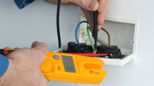
Looking at Figure 1 (other side of this sheet), the lighting circuit is seen to be ‘switched off’ and therefore it should be seen as safe to work within any of the modular fittings repairing or replacing parts – but on closer inspection it can be seen that the NEUTRAL is passing across the switch, not the phase, and therefore the phase section of the terminal block (and any part thereafter) remains live even with the switch in the open* position. This condition is verified (or tested for) by utilising the R1 + R2 test method of linking the Phase to Earth at the DB and testing at the point where a reading would be expected between PH-E. If none is seen (ie: open circuit, > 200Ω), then the test would be moved to the N – E of the same termination point. If a Low Ω reading were obtained at that point this would indicate reversed polarity, and must be investigated further.
(*see note 1)
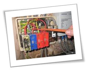
In figure 2 (other side of this sheet), the problem with LIVE POLARITY is highlighted. The terminals in the under-section of a kWh meter are normally as follows: (from left to right)
PH – N – N – PH
You will see in Figure 2 that they are correct from the Main Fuse to the primary intake at the kWh meter, but the secondary side has been wired with the Phase & neutral the wrong way round. In this case the entire neutral bar would be permanently live, and the CB’s would be making and breaking the Neutral – once again giving risk of electric shock under numerous circumstances. This situation is verified by using a set of Approved GS38 Test Lamps and testing from:
PH – N (230V expected)
PH – E (230V expected)
N – E (0V expected)
Finally, look closely at Figure 3. The first rose is wired correctly & how would be expected, although the second is a complete wiring confusion, with the lamp wired across the Neutral and the loop and no wiring in the switch-plate. In this case if the wiring were terminated across a one way switch, it would not in fact turn the lamp on and off – the lamp would be perpetually receiving a phase and a neutral, & therefore stay ‘on’. The far greater problem than a lamp that will not switch off is that there would be 230V present across the switch (ie: if you placed a lamp holder from Common to L1 in the switch it would come on - irrespective of the switched position!) All a bit of a disaster wiring wise– but the correct term to describe the switching remains incorrect polarity – as the switch is not in the phase conductor only.
Note 1* This is why ISOLATION is much more preferable to switching off for maintenance – breaking both poles would eradicate the risk in this case, although the problem would still be in place.

Fuses & Circuit Breakers:
Fundamental defects
Loss of Supply
Tripped CB – Blown Fuse – Internal Fuse
Potential cause: 1.Overload (time to trip or blow will determine the likelihood)
2.Earth Fault (does it re-engage)
3.Faulty device (is it operating functionally – opens and closes)
4.Dead Short – in real terms this could trip a circuit breaker for the circuit
that is shorted, & not the Main fuse.
5.Correct Protective Device
Type B/Type 2 Standard Circuits
Type C/Type 3 Motor Circuits – Inductive Loads
Type D Large Inductive Loads – Large Motors, X-Rays.
Industry
Control Circuits often contain Internal Fuses – what may seem like a loss of supply could be an internal fuse having blown. Single & 3PH motors will react to a restriction in movement by struggling to reach their optimum speed. This will require more power when a restriction is in place & thus create an overload situation.
An earth fault on one phase of a 3 phase supply will disconnect that phase – while the remaining two exert to rotate the apparatus. This is often identified by overheating, buzzing or humming coming from a motor, or the machine thrusting with uneven momentum when attempting to rotate.
Newly Installed work – CB’s tripping once power is energised.
Hopefully the installer will have some indication of the most likely ‘trouble spot’ area within the installation that any fault (earth of short circuit) may have occurred once the Main DB is commissioned and the circuits are switched on – eg: a spur off a ring that was difficult to terminate at the 2nd Fix stage, or a multi-gang switch that had a number of 2 and 3 core cables in the same enclosure, and seemed constricted when the face plate was screwed on.
The same test methods are used for new & existing circuits to locate a fault – but a ‘starting-point’ is the critical element for fast and effective rectification.
Remember ! Information is the key... |
Testing to locate the position of a Fault.
Test 1: Insulation Resistance.
If you are convinced that the Earth is touching the phase (or vice-versa), or the PH is touching the N prior to the load, then you would carry out an IR test at 500 Volts DC between the Ph & E or Ph & N. If a reading of 0.00Ω was seen, then the two cables being tested are in contact with each other. If the reading were less than the maximum for the instrument being used (ie a meter that would normally read >999MΩ was indicating 329MΩ) – and was dropping as the test were being carried out, part of the circuit would be seen as erroneous, and must be further investigated.
Test 2: The ‘Half Test Method’
From the above, if a reading of 0.00Ω was seen, then the two cables being tested are in contact with each other at some point in that circuit. To locate the point the circuit must next be disconnected as near to its mid-point as possible. One side would read >999MΩ, and the other would continue to read 0.00Ω. The healthy side can now be disregarded and the half-test carried out again on the damaged side of the circuit.
If the initial reading were less than the maximum for the instrument being used and continued dropping as the test were being carried out, part of the circuit would be seen as erroneous, and must be further investigated using the half test method. This type of reading often indicates the connection between PH to E is less substantial – possible one strand of wire or a fraction of a cable in contact with a screw.
Murray Loop Test
This is a skilled analysis using a dedicated meter which incorporates a number of variable resistors and an ammeter. It is based on the mathematical detail (part of Ohms Law) which establishes that resistance is proportional to length, so if a

link is placed across the cores of a faulty cable and the variable resistors are adjusted until the Ammeter indicates zero – by utilising the equation below the distance from the link can be established.
Murray Loop Test Equation: A/B = {L+(L-X)}/X
where A & B are variable resistor readings, and L&X cable lengths.
This is good for very long runs, often underground, to determine where a cable is broken as opposed to where a fault is in place.
Discrimination: Conventional Paradigms
A device trips; causing complete or partial loss of Power, where this could have been avoided & only have separated part of the supply from one protected point of the circuit if correct discrimination were in place.
General
It is important to note that DISCRIMINATION is ensuring that the correct device operates when a fault or overload occurs – not, as many mistakenly take it, the nearest or smallest device.
Fig. 1
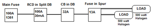
From Fig 1 above, if another five 500watt halogen fittings were added to the circuit controlled by the 13A fused spur, the fuse in the spur would (eventually) overload. However, if the phase in one of the fittings were to touch the earth, in this case the RCD would operate. Theoretically, if a Dead-Short occurred across the cable supplying the Fused spur the Main fuse would operate, although if the halogen lighting brought the load protected by the 32A ring to a figure in excess of its 32Amp rating the CB would disconnect (in due course), etc, etc... so discrimination describes the correct device operating at an essential time in the event of either the cable or the load being rendered unsafe.
Industry
It is always worth remembering that Motor & Control Circuits often contain Internal Fuses – & what may seem like a loss of supply could be an internal fuse having blown.
Fig 2.
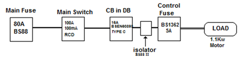
Figure 2 illustrates such a circuit, where a 16A BSEN60898 Type C circuit breaker is wired in line with an Isolator containing a 16Amp BS88 fuse. While these are effectively carrying out the same job, the fuse is part of an isolation device, which is in place for a different purpose to the Circuit breaker at the DB. However, each of the faults listed above would result in a different device operating. For example, a restriction to the movement of the motor, causing it to draw more load may well operate the Control fuse prior to any of the more sensitive devices, while a dead short across the coil to neutral would most lily cause the CB to trip before the 16A BS88 in the isolator (which is closer to the load). Intriguingly in this case the use of a 100mA RCD as a main switch could well give rise to nuisance tripping throughout the life-span of the installation, because the discriminatio0n of the device would be seen to be incorrect.
Conclusion:
There are only a certain number of reasons why a circuit will have ceased to operate as it should. As an Electrician becomes more experienced & encounters more of these faults they come to recognise them very quickly, and then they just need to prove their conjecture by safely testing the circuit to reaffirm their initial assumptions. Rectification is often straightforward once the fault is identified...